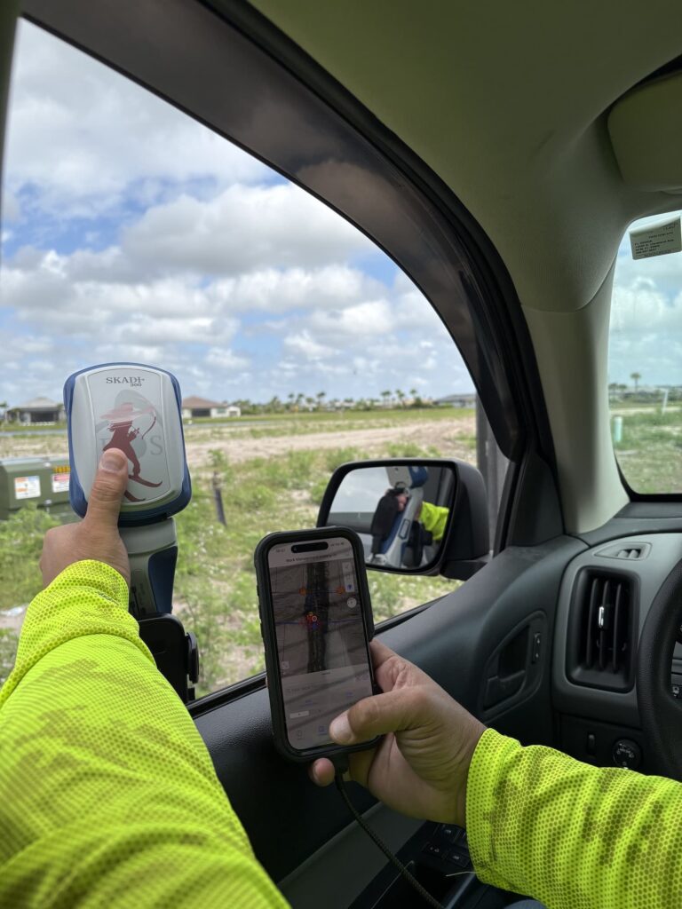
Hardware Capabilities and System Specifications
For high-precision hardware evaluation, data collection requirements and correction sources dictate receiver selection. Multi-frequency processing and RTK carrier-phase differential positioning serve distinct functions within GNSS architectures. Evaluating these capabilities separately prevents treating receiver specifications as an accuracy guarantee.
RF Signal Propagation and Frequency Fundamentals in GNSS Positioning
GNSS uses satellite signals to determine position. A receiver processes measurements from those signals and decodes navigation data, including information about satellite positions and clocks. Those measurements and data allow the receiver to calculate its position.
Satellites transmit radio-frequency (RF) signals. Frequency describes how many wave cycles occur in one second, measured in hertz (Hz). One megahertz (MHz) represents one million cycles per second.
Frequency and wavelength are related but are not the same thing. Wavelength is the distance between corresponding points on successive wave cycles; at the same propagation speed, a higher frequency has a shorter wavelength.
For receiver selection, the practical distinction is between the satellite system and the signals your hardware can process. Tracking more than one constellation is not the same as tracking more than one frequency.
Multi-Constellation Signal Bands and Frequency Allocations
GPS broadcasts signals on multiple frequencies. Galileo also provides navigation signals on multiple frequencies, including a signal at the same center frequency as GPS L1. (1, 2)
The four major global navigation satellite systems (GNSS) that provide coverage in the U.S. use specific radio frequencies within the L-band spectrum (1 to 2 GHz). Broadcasters like Europe’s Galileo, Russia’s GLONASS, and China’s BeiDou operate alongside the U.S. GPS system to improve civilian accuracy and redundancy.
Global Systems
| Constellation / System | Band | Frequency (MHz) | Type & Coverage Role |
|---|---|---|---|
| GPS (United States) | L1 L2 L5 | 1575.42 1227.60 1176.45 | Primary global system. L1/L5 form the civilian dualfrequency core. |
| Galileo (Europe) | E1 E5a E5b E6 | 1575.42 1176.45 1207.14 1278.75 | Fully interoperable with civilian GPS. E1 shares L1; E5a shares L5. |
| GLONASS (Russia) | G1 G2 G3 | 1602.00 (FDMA) 1246.00 (FDMA) 1202.025 | Global system using FDMA channel slots for legacy bands, shifting to CDMA. |
| BeiDou (China) | B1C B1I B2a B2b B3I | 1575.42 1561.098 1176.45 1207.14 1268.52 | Global network. B1C and B2a provide direct commoncenterline civilian interoperability. |
Regional Overlay & Augmentation Systems
| Constellation / System | Band | Frequency (MHz) | Type & Coverage Role |
|---|---|---|---|
| WAAS (US SBAS) Wide Area Augmentation System | L1 L5 | 1575.42 1176.45 | Broadcasts differential corrections via geostationary satellites over North America to ensure safety-of-life civil aviation accuracy. |
| QZSS (Japan RNSS/SBAS) Quasi-Zenith Satellite System | L1 L2C L5 L6 | 1575.42 1227.60 1176.45 1278.75 | Regionally optimizes signals over Asia-Oceania; fully mirrors GPS frequencies for seamless multi-GNSS receiver integration. |
| NavIC (India RNSS) Navigation with Indian Constellation | L5 | 1176.45 | Regional coverage using L5 band for civilian high-precision tracking. |
When evaluating high-precision hardware options, request a full specification sheet covering supported constellations and signal frequencies rather than relying on a generic “multi-frequency” label.
Why multiple frequencies matter
Satellite signals travel through the ionosphere before reaching your receiver. This introduces a frequency-dependent delay that can affect the calculated position. Measurements from the same satellite on two different frequencies allow the receiver to form combinations that cancel the first-order ionospheric effect.
That is the operational reason to consider dual- or multi-frequency processing: it provides measurements that support ionospheric correction, rather than relying only on a single-frequency model. GPS.gov identifies ionospheric correction as an accuracy benefit of combining L1 and L2C in a dual-frequency receiver.
However, multi-frequency support is not, by itself, a promise of centimeter-level accuracy. RTK adds reference-station information and carrier-phase processing for positioning.
Avoid treating receiver options as an all-or-nothing choice between L1-only hardware and hardware that processes every commercially available signal. Confirm the specific signals, correction methods, and upgrade options for the model you are evaluating.
How RTK connects to GNSS accuracy
RTK stands for real-time kinematic positioning. It is a differential GNSS technique that uses carrier-phase measurements and information from a reference receiver at a known location to determine the rover’s position. The rover is the receiver used where you are collecting data.
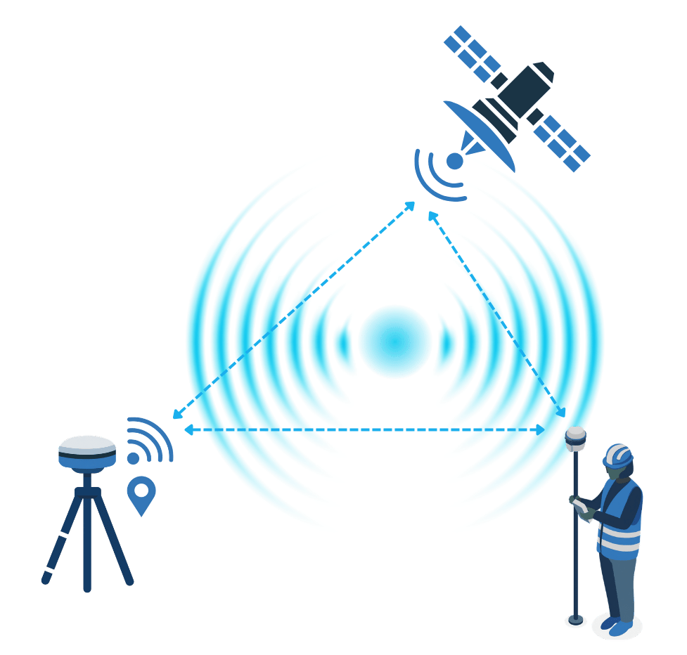
A basic RTK setup has three parts:
- A reference station: A GNSS receiver at a known location.
- A rover: Your field receiver, which also observes satellite signals.
- A real-time communication link: A connection that delivers reference-station information to the rover.
The reference station is not immune to atmospheric effects. Instead, differential processing takes advantage of errors shared by the reference station and rover, reducing their effect on the calculated position. How closely those errors match depends in part on the separation between the receivers.
Carrier-phase measurements provide more precise observations than code measurements, but the receiver must resolve the unknown number of whole carrier cycles, called carrier-phase ambiguities. A fixed RTK solution resolves those ambiguities to integers. Under suitable conditions, RTK can provide centimeter-level positioning.
RTK does not eliminate every source of error. Multipath, interference, receiver noise, and interrupted satellite tracking remain relevant. Obstructions that interrupt tracking can require the receiver to reinitialize its solution.
Evaluate frequency support and RTK capability by their distinct operational functions: multi-frequency tracking mitigates ionospheric delay, while RTK carrier-phase differential processing utilizes reference-station observations to achieve centimeter-level positioning.
Comparative Analysis: Standalone Positioning Versus Differential Correction Modes
Evaluating standalone GNSS alongside differential correction modes clarifies how positioning accuracy, atmospheric correction methods, and signal tracking intersect in technical practice. Comparing these configurations side by side provides a clear structural alignment of high-precision hardware specifications and system capabilities.
| Consideration | Standalone GNSS (autonomous) | WAAS (SBAS) | L1 RTK | L1/L2 RTK | L1/L2/L5 RTK |
|---|---|---|---|---|---|
| Reference-station information | None used | Uses wide-area SBAS ground reference network via satellite broadcast | Uses local base station or RTK network data over internet/cellular | Uses local base station or multi-frequency RTK network correction stream | Uses multi-frequency RTK base/network correction stream |
| Processing distinction | Standard code-based positioning without differential phase processing | Differential code processing using regional SBAS corrections | Single-frequency carrier-phase differential processing with ambiguity resolution | Dual-frequency carrier-phase differential processing; faster ambiguity resolution | Triple-frequency carrier-phase differential processing; robust signal tracking |
| Atmospheric effects | No real-time differential ionospheric cancellation | Broad atmospheric corrections provided by SBAS network | Cancels shared ionospheric errors over short baselines (<10 km) | Eliminates first-order ionospheric delays mathematically via dual-frequency combinations | Superior ionospheric delay cancellation and resistance to interference |
| Accuracy statement | 2–5 meters (autonomous) | 30–60 cm (submeter) | Subfoot to 1–3 cm under optimal clear-sky conditions | 1–3 cm reliable precision | 8 mm centimeter-level accuracy |
| Supported frequencies / constellations | Single frequency (L1); standard constellations | L1 (and L5 SBAS); GPS/WAAS | Single frequency L1; GPS, GLONASS, Galileo, BeiDou, QZSS | Dual frequency L1/L2; major GNSS constellations | Triple frequency L1/L2/L5; all major GNSS constellations |
| Typical use case / application | Basic navigation and low-accuracy mapping | Submeter GIS asset mapping and general field collection | High-accuracy GIS mapping in open field environments | Survey-grade GIS mapping and construction staking | Challenging environments (under canopy, urban canyons) requiring maximum productivity and accuracy |
Evaluating Correction Services and Infrastructure Requirements
Receiver configurations and correction access options represent an integrated system requirements profile. Before selecting high-precision hardware, confirm:
- The correction services available in your actual collection area.
- The receiver signals and correction formats each service supports.
- The communication method and connectivity requirements.
- Account, licensing, and subscription terms.
- Access requirements for the total number of deployed receiver units.
There are numerous commercial correction services available for subscription in most areas of the U.S. Be sure to check with your local state agency or academic institution. These organizations at times provide free or low-cost public corrections.Do not use a statewide exclusion list as a purchasing decision without checking current providers. Eos Positioning Systems® provides an RTK activation code for receivers to be able to use RTK. Confirm receiver pricing separately from correction-service charges before estimating the cost of your configuration.Digital Mapping Group has compiled a map of U.S. RTK corrections, available upon request.
High-Precision Hardware Configuration Options Across the Eos Skadi® and Arrow Series®
Baseline receiver performance delivers ±1.5 ft accuracy under clear-sky conditions. Processing additional frequencies improves accuracy retention in challenging GNSS environments, such as tree canopy and urban canyons, where the higher power level of the L5 signal enhances tracking stability. To evaluate high-precision hardware options, access Eos Positioning Systems’ receiver selection guide.
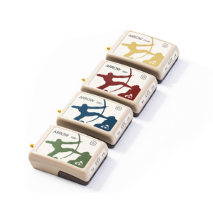
- Arrow 100+ | Skadi 100 = L1 = SBAS – Submeter
- Arrow 200+ | Skadi 200 = L1 & L2 – RTK
- Arrow 300+ | Skadi 300 = L1, L2 & L5- RTK
- Arrow Gold+ | Skadi Gold = All Frequencies + GALHAS – RTK

Technical Consultation and High-Precision Hardware Configuration Planning with Digital Mapping Group
Schedule a technical consultation with Digital Mapping Group to evaluate deployment areas, positional accuracy requirements, correction infrastructure access, and hardware specifications.
Additional Resources
- ESA Navipedia GPS General Introduction
- European Space Agency Galileo navigation signals and frequencies.
- GPS.gov New Civil Signals
- ESA Navipedia RTK Fundamentals